Nacrtak Earthwork usually represents the largest cost component in the construction of low-volume forest roads. Accurate estimates of earthwork volume are essential to forecast construction costs and improve the financial control of road construction operations. Traditionally, earth-work volumes are estimated using methods that consider ground data obtained from survey stations along road grade lines. However, these methods may not provide accurate estimates when terrain variations between survey stations are ignored. In this study, we developed a computerized model to accurately estimate earthwork volumes for the proposed forest roads by using a high-resolution digital elevation model . We applied our model to three hypothetical forest road layouts with different ground slopes and terrain ruggedness conditions.

We examined the effects of various cross-section spacings on the accuracy of earthwork volume estimation assuming that 1-meter spacing provides the »true« earthwork volume. We also compared our model results with those obtained from the traditional end-area method. The results indicate that as cross-section spacing increases the accuracy of earthwork volume estimation decreases due to lack of the ability to capture terrain varia-tions. We quantified earthwork differences, which increased with terrain ruggedness rang-ing from 2 to 21%. As expected, short cross-section spacing should be applied to improve accuracy in earthwork volume estimation when roads are planned and located on hilly and rugged terrain. The grid method of calculation involves drawing a grid onto the plan for the earthwork project.

For each node of the grid, determine the existing and proposed ground level and calculate the cut or fill required. Once the cut or fill depth is calculated, multiply the value by the area of the grid cell. Do this for each square of the grid, then add the volumes together to determine the total cut and fill volumes for the project. Prediction of roadway is one of the main effective factors on fill and cut slope volume, cost and disturbance in forest road constructions. The objective of this study was to develop models for prediction of forest roadway using artificial neural network and multiple linear regression . For this purpose, 192 cross profiles were measured on the Soordar-Vatashan forest roads.

Within each sample, hillside gradient, slope direction, rock share ratio and texture of soil were recorded as the inputs and roadway was recorded as the output. According to coefficient of determination , multiple correlation coefficient and root mean square error and percent error, the ANN was more successful than regression model in prediction of roadway. The grid method involves drawing a uniform grid onto a plan of the earthworks project, and taking off the existing and proposed ground levels at each node of the grid. With these values the average depth of cut or fill required on each cell of the grid is calculated, and the volume for each cell is obtained by multiplying the depth by the cell area.

By adding the volumes for each cell together the total cut and fill volumes for the project can be estimated. Selecting an optimal vertical alignment while satisfying safety and design constraints is an important task during road construction. The amount of earthwork operations depends on the design of the vertical alignment, so a good vertical alignment can have a profound impact on final construction costs. In this research, we improve the performance of a previous mixed-integer linear programming model, and we propose a new quasi-network flow model. Both models use a piecewise quadratic curve to compute the minimum cost vertical alignment and take earthwork operations into account.

The models consider several features such as side-slopes, and physical blocks in the terrain. In addition to improving the precision, we propose several techniques that speed up the search for a solution, so that it is possible to make interactive design tools. We report numerical tests that validate the accuracy of the models, and reduce the calculation time. So how do estimators calculate the volume between two surfaces? This can be a very complicated process since the amount that the elevation of the soil surface changes can vary considerably and irregularly across the site.

The first surface is typically the existing site topography, while the second shows the post-construction site grades. Post construction grades can result from excavation of existing soil, by the placement of additional soil, or by some combination of the two. The volumes required to place soil are typically designated as positive volume while those volumes resulting from excavation are treated as negative volumes. The resultant numbers can be added together to get a cut-to-fill balance for the site. A well-designed site will result in a balanced cut to fill with the net volume of the two equaling zero. Depending on the nature of the site and its proposed earthwork, there are several options available for accurately estimating the resulting earthwork volumes.

Most site excavation takeoffs have historically been performed using paper grading plans and a large format digitizer tablet. Contour lines, spot elevations, and areas were entered into the computer from the blueprint using the digitizer tablet. Once this information is digitized into the computer, site volumes are calculated along with a 3-D model of the existing and proposed site. The digitizer method is the ideal approach if contractors prefer to work with paper plans. However, many contractors are now receiving electronic files instead of paper plans, and the use of on-screen takeoff tools are gaining in popularity. This method involves drawing horizontal and vertical lines over your site plan to divide it into grid cells of equal size.

You then include the existing elevation and proposed elevation for each corner of the grid cells, and work out the difference between the two, as this will be cut or fill depth for that spot. When you've done this for every corner you add them up, average them, and perform further calculations that will end up giving you a total number of cuts and fills. The difference between these two numbers will show you if earth will need to be removed or brought onto site to complete the job. The cross-section method of calculation is a common method used with the 2-dimensional method of mapping. With this method, cross-sections of the existing and proposed land levels are measured at regular intervals across the site. The cut and fill area is determined for each cross-section, then adjacent cross-sections are compared and the averages of their cut and fill areas are multiplied by the distance between them.

This is done for each adjacent pair of sections, then the total volumes are added together to create the complete cut and fill volumes for the project. The cross section method involves plotting cross sections of the existing and proposed levels at regular intervals across the project site. For each of the cross sections, the cut area and the fill area is determined. The volume between each pair of sections is estimated by multiplying the average cut or fill area of the two sections by the distance between them.

Once these volumes have been calculated for each pair of sections the total cut and fill volumes are obtained by adding them all together. This, in turn, allows for the creation of highly accurate Digital Terrain Models. Given the huge number of calculations required, this is a process that can only be done on a computer. The DTMs allow for direct calculation between a surface and a fixed elevation or two such surfaces.

DTMs can also be generated for different soil strata in an excavation, allowing for direct calculation of volumes for each soil type. The slices are aligned perpendicular to a baseline running the full length of the earthwork area. This is usually the site's longest dimension to increase accuracy, but can also be aligned along a property or tract line, utility easement, right of way, roadway centerline, etc. The interval between the parallel slices can vary depending on the size of the site and the designed accuracy of the calculation. The volume of a massive 1,000-acre site development could be calculated with reasonable accuracy with intervals of 100 to 200 feet. A smaller square building lot of fewer than 10 acres would not achieve reasonable accuracy with such a large interval as it would only utilize six slices.

In general, the smaller the site, the smaller the required interval between slices. The triangular prism method starts by triangulating the existing terrain to create a continuous surface of connected triangles. Once both surfaces are complete, the triangulations are merged to create a third triangulation. Once merged, the cut and fill is calculated by taking the volumes of the generated triangles and adding them together. Because of the excellent representation of both the existing and desired terrains, this method presents an excellent representation of volumes for cut and fill projects. In this paper, an optimization program developed to produce an optimum vertical highway profile for a preselected horizontal alignment is described.

The aim of the program was to provide local highway engineers and planners in Singapore with a practical aid for highway geometric design and location analysis. A dynamic programming formulation was adopted to minimize the overall cost, which includes earthwork, land acquisition, materials, and vehicle operating costs. A real-life numerical example is presented to illustrate program application. A TIN surface is any surface that is created using this method. When you create a TIN volume surface, Civil 3D superimposes one TIN surface over another and creates a point at each location where the triangle edges cross. New triangles are then created by connecting the calculated points.

The resulting surface has the same distinctive triangular shapes, but instead of elevations, the values it represents are differences in elevation between the two surfaces. These differences in elevation are referred to as cut when they are negative and fill when they are positive. The Grid Method.The Grid Method is normally used to estimate volumes excavated from borrow pits . Like the Depth Area Method, the Grid Method utilizes thickness measurements over a given area.

Each grid point is treated as the center of a square whose sides are equal to that of the grid interval . The surface slope within the grid square itself is accounted for and approximated by assigning surveyed or proposed elevations to each of the square's corner points. The square is treated as a column that goes directly down vertically through the proposed soil excavation where the four corners align with matching corners located on the proposed surface. Measurements can then be taken to determine the depth of cut or fill at each corner .

Formulas and methods for determining the volumes and areas of regular shapes and surfaces go back at least as far as ancient Greece. Pythagoras and other mathematicians determined those formulas that are still used to calculate the volumes of spheres and pyramids, as well as the areas of curve conic sections. But what was a matter of mystic philosophy to the Greeks is a matter of financial life or death for earthwork contractors. Since there is an inherent error in any estimating earthwork calculation, the contractor must properly manage the resultant unknowns to ensure the success of the project.

With CadTools you can create your own surface models based on objects in the drawing or import triangles from DWG . You can create profiles and cross-sections of multiple surfaces, calculate volumes and plot contours. Once you choose your settings, click ok, and the compute materials list dialogue box opens. Next, pick your quantity takeoff criteria from the list, and the volume calculation method that you would like to use. Set the existing and proposed surfaces you would like in the section below.

Once you have the settings completed, it is time for the next step. Once we create the EG and FG surfaces, we can proceed to create a volume TIN surface. On this surface, we will select the EG as 'base surface' and the FG as 'comparison surface'.

After this, we will have a volume surface in Civil 3D containing accurate cut and fill volumes. The software obtains these volumes by comparing the volume contained between the triangles of the EG and those of the FG. We then just need to open the volume dashboard and add our newly created volume surface. On top of these, one of the most popular tools amongst contractors is the Civil 3D cut and fill analysis. Estimating the earthworks volume often becomes one of the most challenging parts of any construction project. Traditionally, this estimate was a manual process, using cross-sections from topographical surveys.

This method was very time-consuming and often led to substantial errors due to the human factor. MasksandBoundaries are excellent surface display tools. Masks can be useful to exclude an area of a surface from displaying in a drawing but still retain all the surface data used for earthwork calculations. Boundaries can be useful to "reign in" large surface models by excluding areas we do not wish to display or to remove surface data we do not want to include in calculations.
In most cases, this means you need to trim one or both terrain surfaces - either by extruding the border curve of the smaller of them, or by creating an auxiliar "trimming" 3D box . We will also need to make AutoCAD "Surface" objects from all these components to finally generate the resulting 3D solid and read its volume. When you choose create multiple section views, you will notice that section view tables is no longer grayed out. This is because we have already computed the materials list. When you get to this section, please choose total volume for the type of table, and your custom table for the style.

This area also lets you choose the position where you would like the table to be located based on the section view. You can select whether to measure cut-and-fill volumes within some specified distance of the selected line or within the specified area. Whichever option you choose, the heights will be interpolated between line vertices to get a smoothly varying cut height. If measuring within an area, there is also an option to perform multiple cut-and-fill calculations between a range of cut height values. If you choose this option the results will be displayed in a table at the end of the operation so you can see the results of each calculation. There are several great advantages to the triangular prism method.
First and foremost, this method is the most mathematically complete of the three. There are several different methods used to determine the areas of cut and fill, once the sections have been plotted. Perhaps the simplest method is to plot the sections on gridded paper and count the grid cells of the cut and fill areas. Multiplying the cell count by the area represented by each of the grid cells gives the cut or fill area for the section. Other methods include drawing the sections in CAD and exporting areas or calculating areas mathematically using the trapezoidal rule. The spreadsheet included with this article includes formulae which have automated the process of calculating section areas using the trapezoidal rule.

This can save a great deal of time if you are using the cross section method. To create an earthwork construction plan in Autodesk Civil 3D, use the Earthwork Plan Production feature found on the Analyze tab of the ribbon and on the Volume and Materials panel. This tool uses two TIN surfaces to calculate the volume, then inserts a grid with labels and a corresponding table. I have created surfaces for my original ground and my corridor. Both have appropriate boundaryies and the TIN looks good for both.

I am trying to create a volume report through Volume Dashboard. I am able to create the volume surface with no issues but the numbers it comes up with do not seem correct. I can see from my profile that there is a small fill but the software seems to create a fill that is almost half of all the material when my profile shows there is more cut. The problem is, when you finally finished doing the calculations, you found out the 3D model had changed, and it all needed to be redone, starting over again from the very beginning.

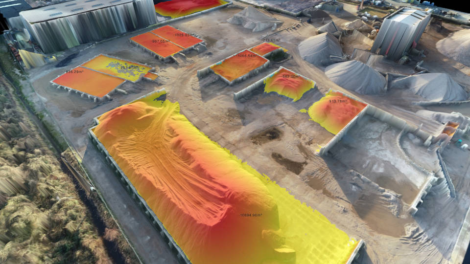
Unfortunately, this usually happened multiple times over the length of the project. Not only did you have to recalculate the volumes, but you also had to update the volume callouts to match the new numbers. The cut and fill process is an extremely useful process for excavation in residential, commercial and roadwork projects. However, while cut and fill makes use of existing terrain, it requires detailed planning to be as effective as possible. To accomplish this goal, project planners need detailed cut and fill maps — that means they need survey equipment to get terrain information and software to process and visualize data in a meaningful way.

If you're using an earthwork software, you may not need to use one of the manual methods above. Instead, the software will run the calculations for you. However, automated systems often use more sophisticated calculation methods, such as the triangular prism method. In these programs, considerable error can occur on the boundaries depending on the extent of the topo coverage. The programs convert the topo into TINS as part fo the 3d model. You also have to use break lines to accomodate walls, curbs, etc.
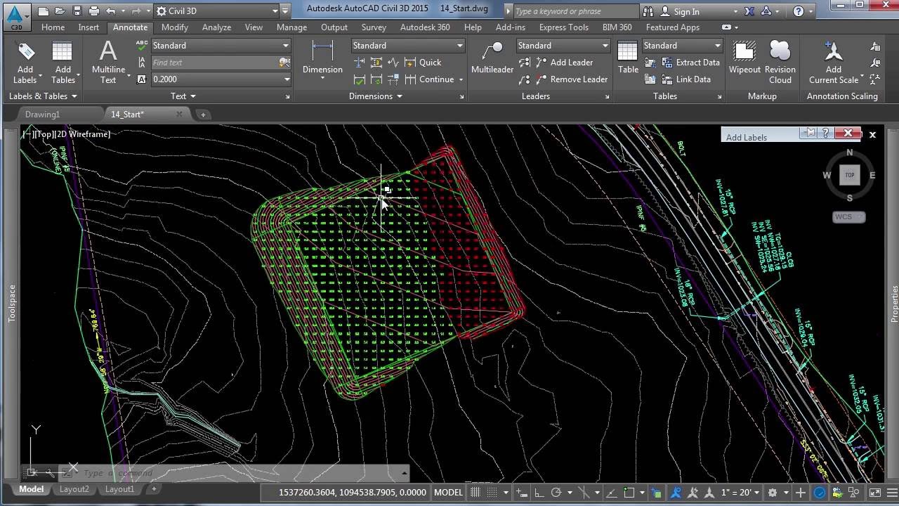
The programs allow you to use the composite, pyramid or grid methods for the earhtwork calcs depending on the type of calculations. In most projects, it will also be helpful to show the cut and fill areas of the project on a plan. This is fairly straightforward in Civil 3D. We just need to open the properties of the volume surface and set a style that has 'elevations' activated. Then we go to the analysis tab, just as we did for surface analysis, and set the elevation banding required.

A standard rule is to use a gradient of red colours for cut and a gradient of greens for fill. This will help the project team understand where there is cut and where there is fill . Multi‐objective analysis is a popular tool to solve many economic, managerial and construction problems. The objective of this research is to develop and implement a methodology for multi‐objective optimization of multi‐alternative decisions in road construction.


No comments:
Post a Comment
Note: Only a member of this blog may post a comment.